(Ⅰ) Measurement of Lens Rim Horizontal Width (Size A)
Size A (frame method) is the max horizontal distance of the lens. Use a vernier caliper to measure the longest part of the inner eyeglass rim parallel to the horizontal axis to determine Size A.
For full-frame glasses, the relationship between the inner frame and the A-size is as shown in the diagram: A = A1 + 2a. Here, “a” is a constant related to the lens size specification. Therefore, by measuring the A1 dimension, we can determine the horizontal size of the lens.
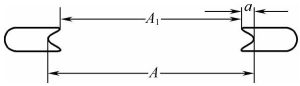
For semi-rimless wire frames, the relationship between the inner frame size and the lens A measurement is as shown in the diagram—the inner frame dimension matches the lens size, so measuring the maximum horizontal inner frame dimension yields the lens A measurement. For rimless frames, measure the lens directly.
![]()
(Ⅱ)Measurement of Lens Height (B-Size)
The measurement method for the lens B-size is the same as that for the A-size, but the measurement direction is the vertical axis of the lens when viewed frontally.
(Ⅲ) Measurement of Lens Frame Circumference
The lens frame circumference is measured using a lens frame measuring device.
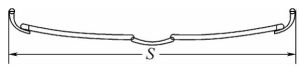
(Ⅳ) Bridge Size (DBL) Measurement
The bridge size refers to the minimum distance between the left and right lenses.The bridge size can be measured using calipers to determine the minimum inner dimension between the two lens rims (C1). For full-frame glasses, DBL = C1 – 2a.
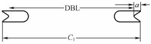
For semi-rimless frames, the minimum distance between the inner rims of the two lenses is the bridge size, i.e., the minimum inner rim distance L2=DBL, while for rimless frames, it is the direct measurement of the distance between the two lenses.
(V) Measurement of Temple – Related Dimensions
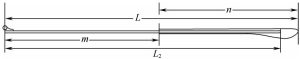
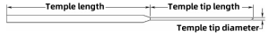
The dimensions related to the temple include the temple length L(temple – tail length), the middle – temple length mmm, the temple – tip length nnn, the width and thickness of the middle – temple part, and the temple – tip diameter.
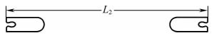
The temple length is the distance from the center of the hinge screw hole to the end of the temple tip. Therefore, it can be directly measured with a caliper. L represents the finished temple length, and L2 is the length of the metal temple after cutting.
These three parameters can all be directly measured with a caliper.
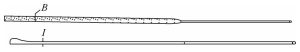
The width and thickness of the temple middle part refer to those at the hinge joint. Also, there are max/min values. Measure the marked positions (width B and thickness I) with a caliper.
(VI) Temple Front Inclination Angle Measurement
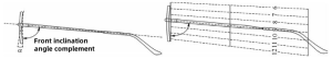
The temple front inclination angle is the tilt angle between the temple and the lens rim when viewing the frame from the side.
Measurement method: Use a front – inclination angle gauge. Rest the inner side of the front lens rim against the base of the gauge, keep the optical axis parallel to the bottom line of the gauge, and move the frame until the centerline of the temple aligns with a scale line on the gauge. The number on this line is the front inclination angle α.
(VII) Frame Width Measurement
The frame width refers to the outer width at the joint of the two temples when viewing the frame from above.
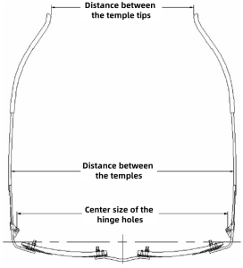
(VIII) Measurement of Open – Temple Shape Dimensions
The open shape of an eyeglass frame refers to the shape viewed from above when the two temples are fully opened. There are three dimensions to represent the open – temple shape: the distance between the centers of the hinge holes, the distance between the middle parts of the temples, and the distance between the tips of the temples. These can be measured with a ruler, steel rule, caliper, or gauge.
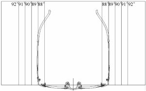
(IX) Measurement of Temple Opening Angle
To measure the temple opening angle, use an angle gauge. Rest the front rim of the eyeglass frame against the side of the angle gauge and move it left – right. Check which line the middle part of the temple aligns with. The corresponding reading on the line indicates the temple opening angle. The tolerance is ±1°.
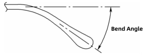
(X) Bent – Temple Angle Measurement
The bent – temple angle refers to the downward – bending angle of the temple tip when viewed from the side.
There are two methods to measure the bent – temple angle:
Method 1: Comparison with a Standard Bent – Temple Gauge
Place the bent temple into a standard bent – temple gauge. If the bent part of the temple fits smoothly and precisely with the gauge, it means the angle of the temple tip matches that of the gauge. The allowable tolerance is ±1°.
Method 2: Using an Angle Meter
Align one side of the angle meter with the centerline of the temple. Adjust the angle meter so that the angle rod aligns with the centerline of the bent part of the temple tip. Then read the angle α indicated by the angle rod on the angle meter. The allowable tolerance is also ±1°.